Design the whole vehicle
An optical surface is only one part of a spacecraft. A useful concept must include its structure, electrical control, thermal path, sensors, communications and protection. Any acceleration estimate must use the mass of the complete assembly, not just a thin active material.
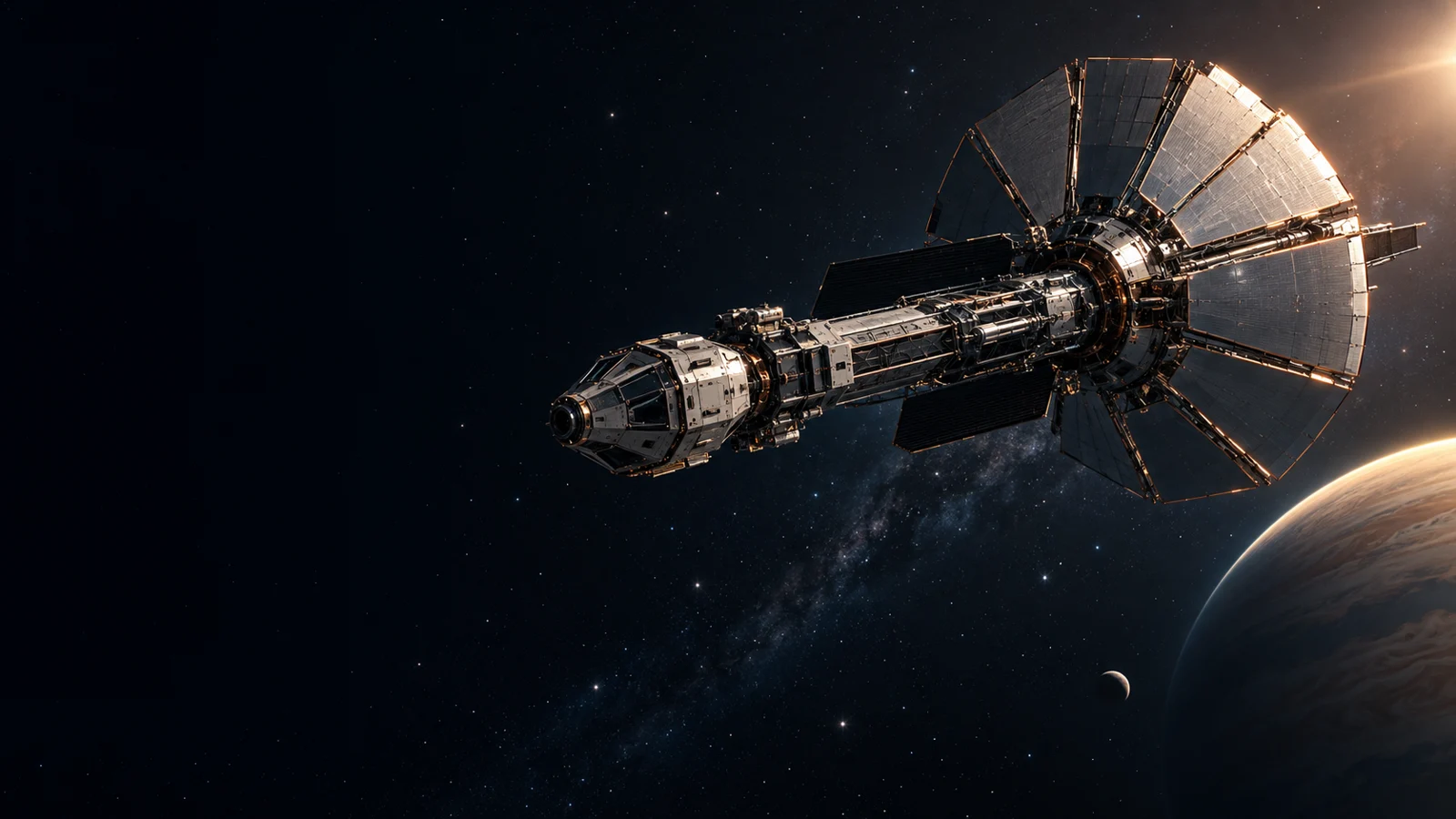
Our illustration organizes these functions around a central structural spine. It does not assign a validated thrust, dry mass, crew capacity or operating temperature. Those quantities must emerge from a mission requirement and a closed engineering budget.
INSPECT THE CONCEPT / SELECT A SUBSYSTEM
Forward payload and shield
A conceptual forward module represents science instruments and environmental protection. Material, thickness and qualification remain unresolved.
Functional illustration only. Markers identify broad areas; this is not CAD, a cutaway of real hardware or a validated design.
Six functions to close
The forward section represents shielding and a science payload. The central bus holds avionics and optical control. Rigid interaction panels stand for a possible means of receiving or redirecting external light. Radiator wings provide a conceptual heat-rejection area. Navigation and communications require apertures with a usable field of view. The spine transmits loads between all of them.
A spacecraft layout must resolve conflicts between these functions. A radiator must see cold space; a protective shield must face the incoming environment; a receiver must track its source. A dramatic silhouette alone cannot meet these competing requirements.
Define where the energy comes from
An externally illuminated vehicle receives momentum from a source outside the spacecraft. An onboard emitter instead expels photons and must carry or generate the required energy. These are different architectures, with different mass and heat budgets. Internal reflections do not create an external momentum source.
The next design deliverable is a requirements sheet covering power intercepted, angular distribution of outgoing light, absorption, duty cycle, full-system mass and a braking strategy. Only then is it useful to optimize the shape.
Questions worth asking
Are these engineering drawings?
No. The cutaway identifies functions and questions. It is not fabrication CAD or a verified vehicle configuration.
Why are there no engine flames?
The depicted concept centers on optical momentum exchange. The illustration does not assign a working propulsion system.
SOURCES & SCOPE / REVIEWED 23 OCTOBER 2026
- A Roadmap to Interstellar Flight — Philip Lubin ↗Directed-energy mission concepts and engineering scope.
- Relativistic spacecraft propelled by directed energy — Kulkarni, Lubin & Zhang ↗Published theoretical treatment; not Metric Flight hardware.
External research is not Metric Flight performance. Concept images and diagrams are illustrative. This project introduces no new company experimental result.
NEXT CHAPTER